
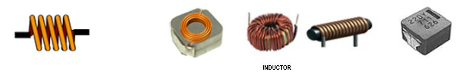
The basic structure of an inductor is to wind the wires into a coil shape, which can convert electrical energy into magnetic energy and store it inside the inductor. The accumulated magnetic energy is determined by the inductance value of the inductor, and the unit of inductance value is Henry (H).
2. The basic structure of inductance
The most basic inductor is an inductor that winds wires into a coil shape, with external terminals at both ends of the wire. In recent years, a large proportion of inductors have been made by winding wires around magnetic cores.
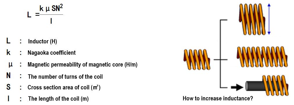
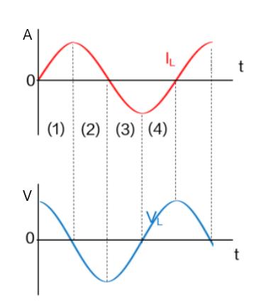
The inductance value of an inductor can be calculated using the following formula:
3. Symbol for inductance
|
type |
|
|
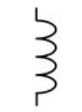
Inductor (without magnetic core) |
 |
|
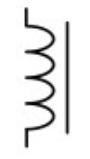
Inductor (iron core)
|
 |
4.1 DC voltage
As shown in the circuit diagram, when the switch is closed and a DC voltage is applied to the inductor, the current will flow to the inductor. As the current flows to the inductor (winding), the magnetic beam generated will also change, and an electromotive force (induced electromotive force) will be generated on the inductor. Basically, an inductor is a separate winding, so it is called "self inductance". This electromotive force is generated in the opposite direction of the current, hindering the increase of the current. On the contrary, once the switch is disconnected and the current begins to decrease, the inductor will prevent the current from decreasing.
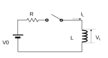
Current (IL) represents the following situation: when the switch is closed, the current will flow out, but due to the obstruction of the increase in electromotive force current, the current will increase at a certain time constant. After the increase, it will depend on the resistance component and there will be a constant current flowing through. Once the switch is opened, the current will decrease, but it will become zero at a certain time constant in the same way.
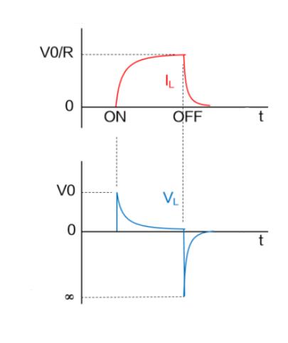
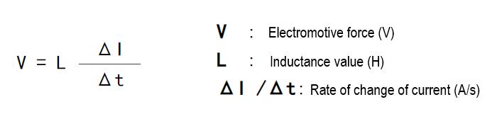
Voltage (VL) represents the electromotive force of the inductor when the switch is closed and when it is opened. As shown in the formula, the rate of change between the electromotive force generated on the inductor and the current ( Δ I/ Δ t) Directly proportional.
As shown in the current waveform just now, when the switch is closed, the current will slowly increase, so the electromotive force will only rise to the power supply voltage. When the switch is turned off, the current is instantly cut off, resulting in a sharp decrease in current and an increase in the rate of change per unit time compared to when the switch is turned on, resulting in a higher electromotive force.
In addition, when the switch is disconnected, the current does not instantly become zero because there is a discharge current flowing through the terminals of the switch due to the high voltage generated by the inductance.
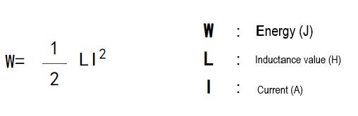
The reason why such a high electromotive force can be generated is because, as mentioned in the beginning of "the so-called inductor", the inductor is able to convert electrical energy into magnetic energy and store it inside the inductor. The accumulated energy can be represented by the following equation, which is directly proportional to the magnitude of the inductance value.
AC voltage
The above description describes that the magnitude of the electromotive force generated on the inductor is directly proportional to the rate of change of the current flowing to the inductor, which is also the same in AC waveforms.
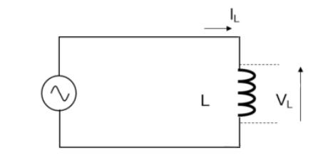
(1) Firstly, when the current rises from zero, the rate of change of the current is maximized, resulting in an increase in voltage. However, the voltage slows down as the current rises, and at the point when the current reaches its maximum (the rate of change of the current is zero), the voltage becomes zero.
(2) When the current starts to decrease from its maximum value, a negative voltage is generated, and when the current reaches zero (the rate of change of the current is the maximum), the voltage is the lowest.
For the areas of (3) and (4), the same situation applies.
When observing the waveforms of current and voltage, if the current waveform is a sine wave, then the voltage waveform is also a sine wave. In addition, it can be clarified that the current waveform deviates by 1/4 cycle compared to the voltage waveform (the phase lag of the current is 90 °).
In response to the large change in current, there will be a larger voltage, and it can also be understood that the higher the rate of change in current, the higher the voltage will increase at high frequencies.
However, the actual voltage of the inductor is the same as the voltage of the AC power supply. Therefore, if we consider voltage as a reference, it can be said that the current flowing through it decreases when the frequency increases at a constant voltage.
That is to say, the higher the frequency during communication, the less easily the current flows through, and the inductor acts like a resistor.
We call this the inductance of a coil (Ω). The impedance and the current flowing through can be represented by the following equation.
tags :
recent posts


scan to wechat:everexceed