The form of the half bridge inverter power conversion main circuit is shown in the following figure:
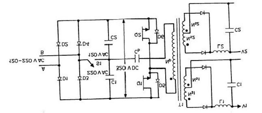
By analyzing the withstand voltage of the switch tube and the primary voltage of the transformer when two switch tubes are alternately turned on and off using a sequential circuit, it is known that the required withstand voltage of the switch tube is Vac; The primary voltage of the transformer is 1/2Vdco
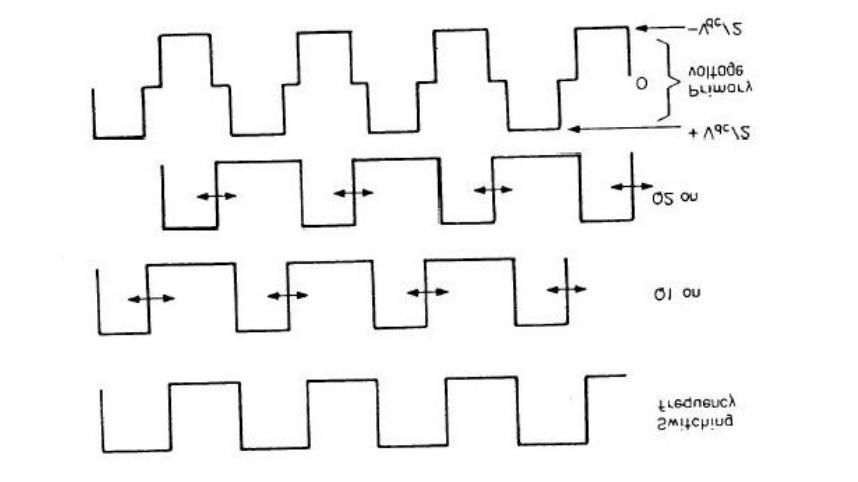
The working waveform is as follows:
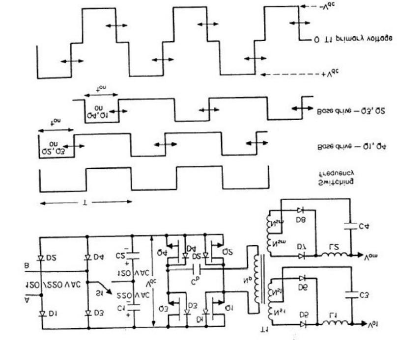
The difference between the full bridge inverter power conversion main circuit and the board bridge circuit is that two other identical switch transistors are used to replace two capacitors, that is, the inverter switch circuit is composed of four switch transistors. Similarly, by analyzing the timing circuit, it can be concluded that the required withstand voltage of the switch transistor is Vac; The primary voltage of the transformer is ± Vdco
As shown in the following figure:
By understanding the characteristics and working principles of the two circuits, you can compare their advantages and disadvantages.
First of all, it is very convenient to see a clear difference from the circuit diagram, that is, the number of switch tubes is different. The number of switching tubes in the half-bridge circuit is small, and the cost is correspondingly low. The full bridge circuit has 4 switch tubes, and two sets of phase opposite drive pulses are required to control two pairs of switch tubes, which inevitably leads to the complexity of the drive circuit. Because there are only two pipes in the half-bridge circuit, there is no simultaneous on-off problem, and its anti-imbalance ability is strong, that is to say, the duty requirement is not very high, so the drive circuit is much simpler than the whole bridge.
When it comes to anti-unbalance ability, we can look at the schematic diagram again, when the half-bridge circuit works at 120VAC, the switch in the middle of the capacitor is closed, and the problem of unbalance is mainly solved by separating the straight capacitor C. When the magnetic flux is unbalanced, there will be a direct current bias in the line. When the direct current bias is large to a certain extent, there will be magnetic flux saturation. With the addition of this direct capacitance, direct current can not pass through to achieve the purpose of anti-imbalance. On the other hand, when there is no straight capacitance, there will be a magnetic flux imbalance, that is, there will be remanent magnetism in the core, the magnetic flux cannot be restored to zero, and the remanent magnetism accumulates to a certain extent leading to core saturation. With this capacitor, when the transformer coil continuous flow energy is too much, it will charge C (CC: the voltage at both ends is certain, so the absorbed energy is also certain), so that the excess energy will not be stored in the coil, forming remanence, so as to solve the problem of magnetic flux imbalance at this time the working principle of the full bridge and half bridge is very similar. When the half-bridge circuit operates at 220VAC, there is no need for the presence of a straight capacitor. Because the voltage at the midpoint of the two filter capacitors is floating at this time, it can automatically adjust the circuit on both sides to achieve balance. When the inductance continues to charge C. in a certain cycle, there is too much energy, and the voltage at both ends of C will be a little higher, and the energy that would have generated residual magnetism will be stored in the capacitor, and the voltage at both ends of C will be correspondingly lower. When the next cycle C is discharged, because the duty is unchanged, it will not release all the excess energy, that is to say, C, the voltage at both ends will still be a little higher than the normal value, but it is not so much higher, by C discharge, because its voltage is lower than the normal value, the release of energy will be less, continue to reduce the voltage at both ends of C until a new balance is reached. Simply put, the two capacitors automatically distribute the excess energy in the transformer until it is balanced without remanence.
The application of half-bridge and full-bridge circuits is also different. We can first look at the voltage waveform of the primary side of the transformer, the primary side voltage of the half-bridge circuit transformer is 1/2Vc, and the primary side voltage of the full-bridge circuit transformer is Vdc. P=VDI, in order to output the same power, the input current of the half-bridge circuit is twice that of the full-bridge circuit; In other words, if their switching currents are the same and the power input voltage is equal, the output power of the half-bridge will be half that of the full-bridge. Therefore, the half-bridge circuit is not suitable for high-power inverter circuit. Moreover, due to the difference in the input voltage and current, there are also certain differences in the design of the transformer, the original side diameter of the half-bridge circuit transformer is thicker, and the number of turns of the original side of the full-bridge circuit is relatively more. Compared with other circuits, half-bridge circuit and full-bridge circuit have a common advantage that they do not need a drain resistance, and the energy stored in the leakage inductance will directly feed back to the BUS, and the efficiency of the circuit is relatively high.
tags :
categories
recent posts


scan to wechat:everexceed