A telecom base station power system is a high-reliability -48V DC UPS system that ensures uninterrupted operation of communication equipment. It combines AC input distribution, high-frequency rectifier modules, battery backup, DC distribution, and monitoring control. When grid power is normal, rectifiers supply DC power and charge batteries. When power fails, batteries instantly take over without interruption. When power returns, the system automatically recharges batteries and resumes normal operation.
· Base stations use -48V DC power systems, not AC UPS systems
· The system is designed for zero-interruption power switching
· It consists of five core subsystems
· Batteries provide instant backup power during outages
· Rectifier modules convert AC to stable DC power
· Intelligent monitoring ensures fully automated operation
· Protection systems prevent damage from electrical faults
A modern telecom base station uses a five-stage DC UPS power architecture:
· AC input power distribution
· High-frequency rectifier system (AC to DC conversion)
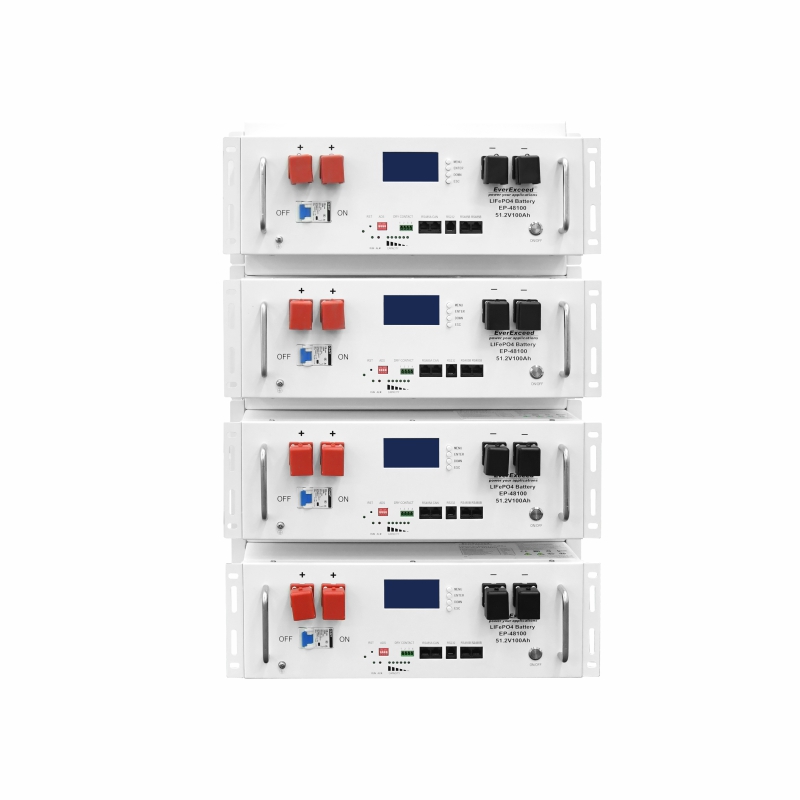
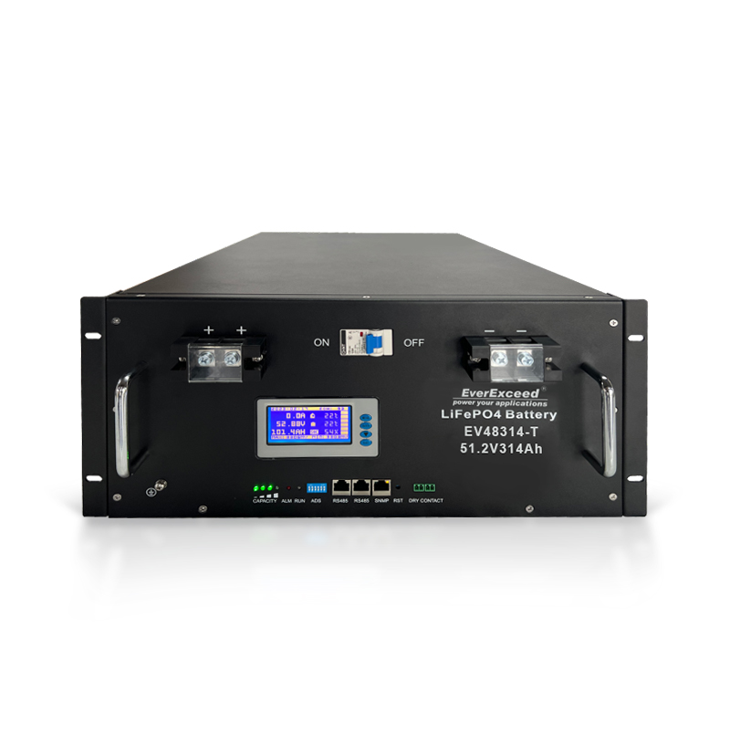
· Battery energy storage system
· DC output distribution system
· Power monitoring and control system
The final output is a stable -48V DC supply, powering all base station equipment such as:
· BBU (Baseband Unit)
· RRU (Remote Radio Unit)
· Transmission equipment
· Monitoring systems
· Cooling and auxiliary devices
This is the entry point of the system.
Main functions:
· Accepts 220V / 380V AC power input
· Provides circuit breakers and protection
· Includes surge and lightning protection
· Filters power disturbances
· Supports dual power input switching (in some sites)
Purpose:
Ensures stable and protected power delivery to downstream systems.
This is the core energy conversion unit.
Functions:
· Converts AC power into stable -48V DC output
· Supports hot-swapping for maintenance
· Multiple modules operate in parallel with load sharing
· Provides voltage regulation and current limiting
· High efficiency (up to 95%+)
Key feature:
Even if one module fails, others continue supplying power without interruption.
The battery system is the backup energy source.
Functions:
· Stores energy during normal operation
· Instantly supplies power during grid failure
· Stabilizes DC voltage and reduces fluctuations
Operating modes:
· Normal mode: float charging
· Outage mode: discharge backup power
Typical design:
Provides 3–8 hours of backup time depending on site configuration.
This is the output power distribution hub.
Functions:
· Distributes -48V DC power to all equipment
· Includes circuit breakers and fuse protection
· Separates different load branches
Supplies power to:
· Baseband units (BBU)
· Remote radio units (RRU)
· Transmission systems
· Monitoring and auxiliary systems
Each branch is independently protected to prevent system-wide failure.
This is the “brain” of the power system.
Functions:
· Real-time monitoring of AC input and DC output
· Battery voltage, current, and temperature monitoring
· Charging mode control (float/equalization charging)
· Fault alarms and remote reporting
· Rectifier module coordination and load balancing
· AC power enters the system
· Rectifiers convert AC to -48V DC
· Equipment is powered directly from DC bus
· Batteries are in float charging mode
Result:
Stable operation with batteries fully charged and on standby.
When grid power fails:
· Rectifiers stop working
· Batteries immediately take over load supply
· Transition is instant with zero interruption
System behavior:
· Batteries discharge to maintain -48V bus stability
· Monitoring system calculates remaining capacity
· Low voltage protection prevents deep discharge damage
Result:
No service interruption occurs.
When grid power returns:
· Rectifiers restart automatically
· Load is powered by rectifiers again
· Batteries switch to charging mode
Charging behavior:
· Fast charging (equalization mode) if battery is low
· Float charging after full recovery
Result:
System returns to stable standby state automatically.
The system uses three key charging strategies:
· Used during normal operation
· Maintains full battery charge
· Prevents self-discharge and degradation
· Activated after discharge events
· Fast charging mode
· Balances battery cell differences
· Adjusts charging voltage based on temperature
· Prevents overcharging or undercharging
The system includes multiple safety protections:
· Input overvoltage and undervoltage protection
· Output overload and short-circuit protection
· Battery over-discharge protection
· Surge and lightning protection
· Module redundancy protection
These mechanisms ensure continuous safe operation even under fault conditions.
· Native telecom equipment operates on DC power
· DC systems have higher efficiency (no inversion stage)
· Zero switching delay during power failure
· No frequency or phase synchronization issues
· Better reliability for outdoor unattended environments
· Improved stability during grid fluctuations
|
Feature |
AC UPS System |
-48V DC UPS System |
|
Conversion stages |
Multiple (AC-DC-AC) |
Single (AC-DC) |
|
Efficiency |
Lower |
Higher (up to 95%+) |
|
Switching delay |
Present |
Zero |
|
System complexity |
Higher |
Lower |
|
Telecom suitability |
Limited |
Standard |
|
Reliability |
Medium |
High |
In a typical telecom site:
· 95% of time: rectifiers supply stable DC power
· During outage: battery system instantly takes over
· During recovery: system automatically recharges batteries
· All operations are fully automated without human intervention
It is a -48V DC UPS system that provides uninterrupted power to telecom base station equipment.
To ensure continuous operation during grid power failures.
They convert AC power into stable -48V DC power.
Typically 3–8 hours depending on configuration.
Because DC systems are more efficient, stable, and designed specifically for telecom loads.
A Global Leading Manufacturer of Customized AC/DC Power Solutions
20+ Years of Battery Manufacturing Experience
10+ years System Integration Experience
categories
recent posts


scan to wechat:everexceed