Off-grid telecom base stations in remote areas such as mountains, islands and deserts cannot rely on grid power supply. Instead, they use a hybrid energy system combining solar power, energy storage batteries and diesel generators.
The system uses solar power as the preferred energy source. When solar generation is insufficient, the battery provides backup power. When battery SOC drops to the preset threshold, the generator automatically starts to supplement energy.
Through -48V DC bus architecture, battery backup management and multi-level alarm logic, the system ensures continuous operation of telecom equipment in areas without stable power coverage.
An off-grid telecom base station energy storage system consists of five core components:
|
Component |
Function |
|
Solar PV Module |
Converts solar energy into DC power through an MPPT controller for battery charging or directly supplying loads |
|
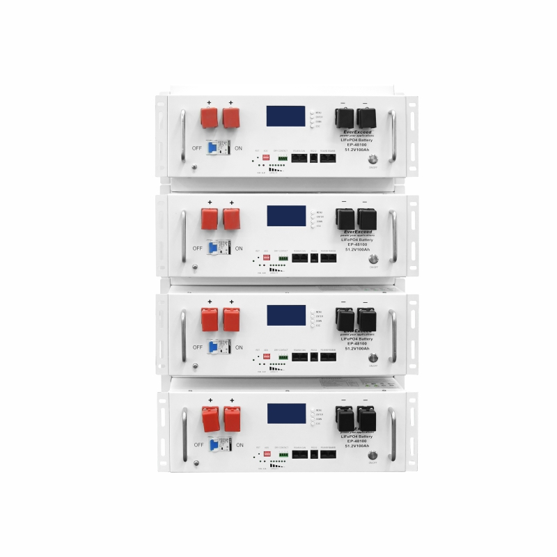
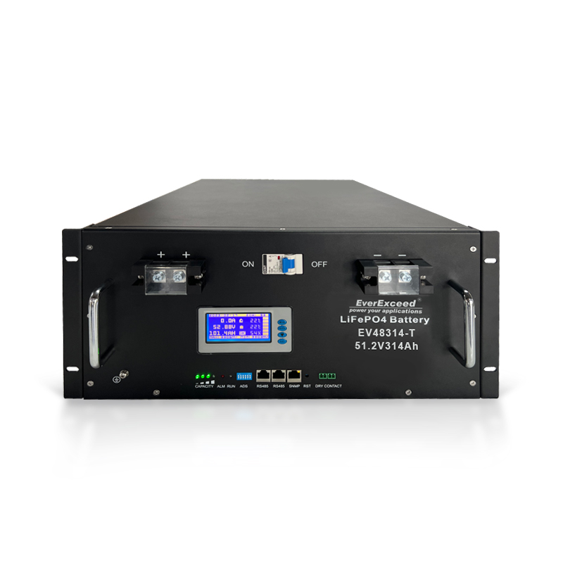
Energy Storage Battery |
Stores energy and supplies power when there is no sunlight |
|
Rectifier Module |
Converts AC power from generator or grid into -48V DC power for loads and battery charging |
|
Generator / Inverter |
Provides additional energy when battery power reaches the warning level |
|
EMS Energy Controller |
Coordinates energy flow and manages power switching, backup operation and alarm logic |
In off-grid areas, solar power, energy storage batteries and generators work together to maintain continuous telecom operation.
All system components are connected to the same -48V DC bus.
The solar controller, rectifier modules, battery system and loads share the same voltage platform.
This architecture provides:
· Simple system structure;
· Flexible expansion capability;
· Continuous power supply when one energy source fails.
Any available energy source can supply power to the DC bus, while other energy sources can compensate when one source becomes unavailable.
The off-grid telecom energy system follows a priority-based energy management strategy.
The normal operation sequence is:
1. Solar power
2. Battery power
3. Generator power
Solar power is used first because it is the cleanest energy source.
When solar generation is insufficient, the battery discharges to support the load.
When battery SOC decreases to the preset threshold, the system automatically starts the generator.
When solar power recovers or grid power becomes available, the system switches back to solar or grid power operation.
The generator does not start immediately when battery SOC reaches the threshold.
The system evaluates multiple conditions, including:
To avoid frequent generator startup and shutdown, the system uses a delay confirmation mechanism.
For example, when SOC remains below the threshold for a certain period, such as 5 minutes, the generator starts.
This prevents unnecessary generator operation caused by temporary solar fluctuations.
After the generator starts, the battery continues to participate in power supply.
The generator and battery work together to support the load, while additional generator energy charges the battery.
When battery SOC recovers to a safe level, such as 70%, and the load remains stable, the system stops the generator and returns to solar plus battery operation.
The whole process provides smooth power transition without affecting telecom services.
Accurate SOC estimation is the foundation of battery management.
The system estimates battery SOC through:
For lithium batteries, voltage alone cannot accurately determine SOC because the voltage platform is relatively stable.
Therefore, the system needs coulomb counting for accurate calculation.
During full charging, the system automatically calibrates SOC to 100% to reduce accumulated errors.
Battery cycle life is closely related to discharge depth.
The deeper the discharge, the shorter the battery cycle life.
Therefore, off-grid telecom systems usually set multiple discharge protection thresholds.
|
Protection Level |
SOC Example |
System Action |
|
Soft Threshold |
30% |
Sends low battery alarm and starts generator priority strategy |
|
Hard Threshold |
20% |
Disconnects non-critical loads and keeps main telecom equipment running |
|
Extreme Protection |
10% |
Disconnects all loads and keeps only BMS operation |
This strategy protects the battery from excessive discharge while extending the backup time of critical communication equipment.
The system calculates remaining backup time according to:
The estimated backup time helps operators make maintenance decisions.
When generator operation is unavailable or fuel supply is delayed, operators can reduce non-critical services to extend the operation time of core telecom equipment.
The alarm system classifies different conditions according to fault severity and response requirements.
|
Alarm Level |
Purpose |
Examples |
|
Level 1 Critical Alarm |
Requires immediate intervention |
Low battery voltage, generator startup failure, complete rectifier failure, abnormal DC bus voltage |
|
Level 2 Warning Alarm |
Requires attention and scheduled maintenance |
Low SOC, single rectifier module failure, low PV output, high battery temperature |
|
Level 3 Information Alarm |
Provides maintenance reference |
Fan speed abnormality, filter warning, temporary communication interruption, battery balancing |
Different alarm levels trigger different response strategies.
Level 1 Critical Alarm
Critical alarms require immediate action. Trigger conditions include:
After triggering, the system sends notifications through SMS, email or mobile applications and can automatically execute emergency actions such as disconnecting non-critical loads.
Level 2 Warning Alarm
Warning alarms indicate conditions requiring attention but without immediate shutdown risk.
Examples include:
These alarms are sent to maintenance personnel for scheduled handling.
Level 3 Information Alarm
Information alarms are mainly used for operational reference.
Examples include:
These records are stored in system logs and used for preventive maintenance.
The alarm system includes delay confirmation and alarm suppression functions.
During normal operations such as generator startup or system power-on, related alarms can be temporarily suppressed to prevent false alarms.
When temporary system fluctuations occur, alarms are delayed before activation to reduce unnecessary notifications.
All operating parameters of the off-grid telecom energy storage system can be transmitted through 2G/4G networks or satellite communication links.
The monitored data includes:
Operators can view real-time data and historical trends through Web platforms or mobile applications.
Remote monitoring reduces site visits and improves maintenance efficiency for distributed telecom sites.
An off-grid telecom base station uses solar power, energy storage batteries and diesel generators to maintain continuous operation in areas without grid power.
The system consists of solar PV modules, energy storage batteries, rectifier modules, generators/inverters and EMS controllers.
The system prioritizes solar power, uses batteries when solar generation is insufficient, and starts the generator when battery SOC reaches the preset threshold.
The generator starts after the system confirms that battery SOC remains below the preset threshold for a certain period.
The -48V DC bus connects solar controllers, rectifier modules, batteries and loads on the same voltage platform, enabling continuous power supply.
The system uses multiple SOC thresholds to provide warnings, disconnect non-critical loads and finally protect the battery from irreversible damage.
System data is transmitted through communication networks and displayed on Web platforms or mobile applications for remote monitoring.
A Global Leading Manufacturer of Customized AC/DC Power Solutions
20+ Years of Battery Manufacturing Experience
10+ years System Integration Experience
categories
recent posts




scan to wechat:everexceed