As a means of protection, most lithium battery systems of almost any string voltage require a
battery management system (BMS) to maintain the cell operating conditions within the limits. These can range in complexity from just cell balancing to ones that monitor cell voltage; cell temperature and current; and, through the use of either semiconductor switches or relays, will disconnect the battery pack from the UPS if any of the monitored variables exceed their operating limits.
When interfacing a
lithium battery system to a
UPS, it is vital to know and understand the limits at which the BMS will disconnect the battery. Many of the BMSs will provide a warning if the operating conditions are approaching these limits before any action is taken. In this manner, it is possible to take some action to avoid having the battery disconnect from the UPS. The BMS will generally not reconnect the battery until the conditions that caused the action are removed. A second reason for having a good understanding of the limits is to make certain the UPS, in normal operation, will not exceed them. Taking care to verify the limits will not be exceeded by the UPS is a good practice and good system design.
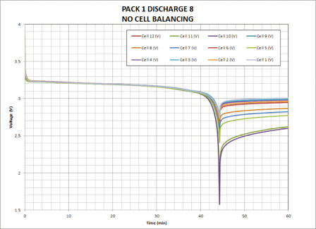
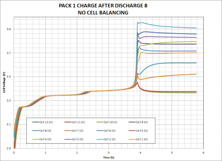
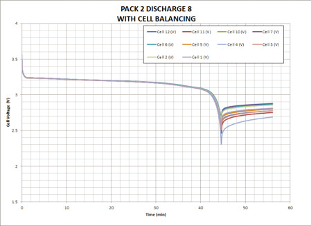
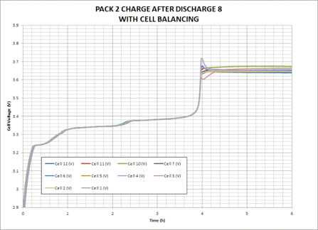
Figure: 1
The following is a brief description of the functions contained in a typical BMS.
Cell balancing: The purpose of cell balancing is to maintain the terminal voltage of each cell, or bank of parallel cells, in the series string approximately equal. Since cell voltage bears some relationship to capacity, with lithium chemistries, keeping these equal will tend to maintain the capacity of each cell equal. This then will serve to prevent weaker cells, those with lower capacity, from being over-discharged. Likewise, cells with higher capacity will not become overcharged. The importance of cell balancing can be seen in Figure 1. Here, a discharge and charge cycle of two LFP packs containing 12 cells in series and 3 in parallel is shown.
On the discharge plots, note some cell voltages in the pack with no balancing decreased below 2.0 V, the minimum limit, near the end of the discharge. This is over- discharging and was starting to occur after only the eighth cycle. In the pack with cell balancing, the voltage decreased to 2.5 V for most of the cells, with one reaching 2.3 V before the discharge ended. All cells are substantially above the 2 V limit.
During charging, after the eighth discharge, note the spread in cell voltages of approximately 0.59 V for the pack with no cell balancing. One cell nearly reached the float voltage limit of 4.0 V. Above this limit is overcharging. With the pack containing cell balancing, the cells are tightly grouped around the float voltage of 3.65 V.
Measurement function: Cell voltage, as shown in Figure 1, is one of these. The purpose of this measurement is to make sure the cell voltages are close enough to each other that the battery can be charged and discharged over the intended range of operation. In some instances, the BMS may not allow charging or discharging, at least not at rated load, until the cell voltages are within some predetermined range of each other. Another measurement is current through the cells. There are usually maximum charge and discharge current limits that if exceeded will trigger a warning and possibly disconnect the battery from the UPS if the condition persists for some prescribed period of time.
The third measurement is cell temperature. When evaluating a battery system for use with a UPS, it should be a requirement that the case temperature of one or more cells is measured. Due to the rapid rise of temperature in the case of a thermal event, an (internal) air temperature measurement may not be fast enough, or sensitive enough, to detect the onset of thermal runaway and take action to disconnect the battery. The BMS will protect the battery from excessive temperatures by signaling when the cell temperature is nearing or has reached the maximum and ultimately disconnect the battery from the UPS if the maximum is reached. Other action that is sometimes taken by a BMS is to limit or postpone charging of the battery until the temperature has decreased sufficiently from the limit.
Some BMS models may also provide a measurement of state of charge (SOC) and an indication of the state of health (SOH) of the battery system. The SOC is obtained by measuring the charge, in Amp hours (Ah) removed (discharging) and replaced (charging). Charge is usually measured by integrating the current into or out of the battery with respect to time. Starting with a known value of available charge, the SOC is just the ratio of the net charge (discharged Ah – charged Ah) to the available charge. The SOH is an indicator of the amount of degradation or aging that has occurred since the battery was new. The basic approach is to determine how much the available charge is decreasing with age. A test discharge, starting from the fully charged state, is usually used to make this estimate. Capacity loss as the battery ages is sometimes referred to as capacity fade.
If you are looking for a battery with not only long cycle life, uninterrupted discharging performance, fast charging capability, higher energy density, but also if you need a lithium battery which will give you worry free operation, and less stress regarding the safety, EverExceed lithium iron phosphate batteries are the best choice for you, because
EverExceed LFP batteries built in world class BMS inside and they guarantees you absolutely NO FIRE, NO EXPLOSION!