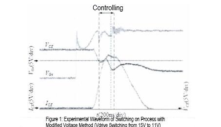
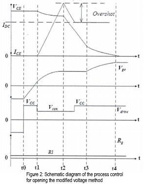
Unlike the resistance method, the voltage method involves changing the driving voltage during the control phase to control voltage and current overshoot. There are approximately two methods to change the driving voltage. One is to achieve the change by dividing the driving voltage through a resistor, and the other is to change the output signal in the control chip (DSPFPGA), and then convert it into an analog signal through the D/A chip to change the driving voltage. The schematic diagram of the process control for switching on the voltage method is shown in Figure 2, and the experimental waveform is shown in Figure
The control method for the opening process of the voltage method and the resistance method is basically the same. The control stage is the same, starting from the rise of ICE and ending with the reverse recovery current of the upper transistor reverse diode.
However, the voltage method is to change the driving resistor.
The schematic diagram of the voltage method shutdown process control is shown in Figure 4, and the experimental waveform is shown in Figure 3.
Figure 3: Experimental waveform of the switching process using the modified voltage method (drive switching from -10V to 2.5V)
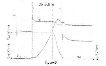
Figure 4 Schematic diagram of voltage method shutdown process control
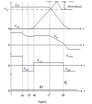
Just like the resistance method, the voltage method is also controlled from the VCE rising during the shutdown process until the ICE drops to near zero and ends the control.
The advantages of changing the voltage method to multi-stage driving have been discussed in detail earlier, and their disadvantages are similar to that of changing the resistance method. Below are the disadvantages:
1: There are two existing methods for changing the driving voltage during the control phase: one is to change the driving voltage by switching the voltage divider resistor through a switch (MOSFET); Another method is to change the driving voltage through a D/A chip. The former has the same problem as the voltage control method, where it is difficult to isolate the signal of the control switch from the power circuit and the signal is easily affected by the noise of the power circuit. The latter has the problem of increasing the cost and circuit complexity of the D/A chip, while increasing the delay of the control circuit and
affecting feedback control.
The second point is that feedback control during the activation process is difficult to achieve, just like changing the resistance method, control must start from the moment when ICE starts to rise. Otherwise, there will be two situations: 1. If the driving voltage is high, just like changing the resistance method, ICE overshoot will be higher. If the driving voltage is low, it will cause a decrease in ICE and even cause IGBT to turn off by mistake. Analysis of specific reasons:
The equivalent model of the IGBT driving circuit in this stage is the same as the equivalent model in analyzing the shortcomings of the modified resistance method, as shown in Figure 2.20. Due to the small size of Rg, Ig is much larger
than IgC. Therefore, when analyzing defects in the modified voltage method, the influence of IgC can be ignored. This simplifies the equivalent model and only requires the driving circuit. Due to the small Rg, it is necessary to consider
the existence of parasitic inductance Lg in the driving circuit. The simplified model is shown in Figure 5.
Figure 5 Simplified model for the control stage of the voltage method opening process
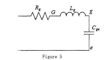
If the driving voltage during control is high, it will take a period of time (approximately tens of ns) for Ig to decrease due to the presence of parasitic inductance Lg in the driving circuit. At this stage, Vge will still rise at a faster rate, so it is not possible to reduce the overshoot of ICE very low. If you want to control ICE overshoot very low, you need to reduce the driving voltage very low, even lower than the current Vge. This will cause ICE to drop, and even cause false shutdown, which will affect the normal operation of IGBT. In order for IGBT to work normally, the driving voltage during the control phase should be at least greater than the Vge before control, which will prevent ICE overshoot from being reduced to a lower level. Therefore, a large IGBT current margin still needs to be left in the circuit design.
The third point is that it is difficult to change the driving voltage Vcom during the control phase, and different control effects (different voltage and current overshoots) cannot be achieved. Some literature proposes the method of adding D/A chips to digital control circuits to change Vcom. However, this not only increases cost, but also increases the delay of the control loop, which may lead to inaccurate or even ineffective control. It cannot be considered a good method and cannot be used in practical applications.
categories
recent posts


scan to wechat:everexceed