AC Power Systems have plenty more units, terms, measurements, interesting waveforms and math to describe their behavior. Any formulas presented here are for reference and validation only. The intension of this paperis convey the concept without having to seriously crunch numbers. All the terms and formulas interweave so itis difficult to create a flow of one topic to another without skipping around a bit.
Generally the goal of the electric utility company is to provide a sine-wave voltage to your building at a fixed frequency, fixed voltage, and ideally, pure containing no harmonics.
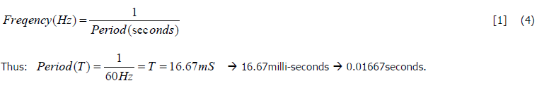
The frequency is how many cycles are completed in 1second. The unit for frequency is (Hz). In the US, ourgrid operates at 60Hz, AKA 60cycles per second. The duration in time of one complete cycle is called theperiod. Typically the frequency is guaranteed +/- 2% (typical +/-0.1Hz). In fact, if the utility spends 15min out of the day sending out 59.5Hz, they will generally try to also spend 15min out of the day at 60.5Hz to make upfor it. Many older analog wall clocks were driven off of the line frequency because the grid generally is just that good.
The power generating utility has a goal to deliver voltage with very good regulation. If you put a high current load on the system, the voltage should have very little drop. Typically, voltage regulation up to a building entrance will be +/- 3%. When visiting a customer be observant of what is going on at the site. If you notice the lights dim as a high-powered load is energized, you have poor voltage regulation.
Another goal is to deliver voltage with as low Total Harmonic Distortion (THD%) as possible as to yield a near perfect AC sine wave. A pure sine wave contains no harmonics at all. Any harmonic content changes the shape of the delivered voltage waveform, and that is essentially the definition of distortion. According to IEEE-519-1992, the utility must generally deliver voltage with less than 5% THD up to the Point of Common Coupling.
(PCC) The PCC is basically the lowest voltage utility distribution node that both you and a neighboring building share. See IEEE-519-1992.

Where (t) is the time interval vector and (f) is the frequency, p =3.14159, (t) is time along the X-axis, and VPEAK is the highest voltage at the top of the sine wave peak.
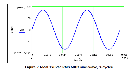
The sine wave above in Figure 2 was generated perfect, containing no harmonics, shown over 2 complete cycles. In casual conversation, Engineer’s hardly ever refer to the sine wave in Figure-2 with Equation (5). It should simply be called a 120VRMS 60Hz sine wave. This is what the voltage coming out of your receptacle athome should look like if viewed on an oscilloscope.
Because the waveform is pure containing no harmonics, one may use the following easy formula to calculatethe RMS or effective value from the waveform:
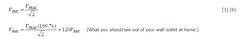
Remember that formula (6) is effective for pure sine waves only! As soon as the waveforms contain harmonicsand is barely visibly distorted, the simple equation no longer gives usable results.
If you have any requirements or any kind of query regarding the UPS solutions for your applications, feel free to communicate with our dedicated team at any time at marketing@everexceed.com.
categories
recent posts


scan to wechat:everexceed