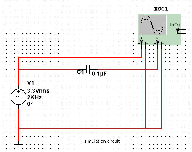
For low-frequency circuits, resistors and capacitors can be analyzed as ideal devices. However, in high-frequency circuits, these two devices will not be "ideal". Today, our main discussion is about the issue of AC capacitors, which are commonly known as AC coupling capacitors. Their main function is to filter out the DC component of the signal, which is symmetrical about the X-axis. Below, we will simulate using MULTISIM, and the specific simulation circuit is as follows:
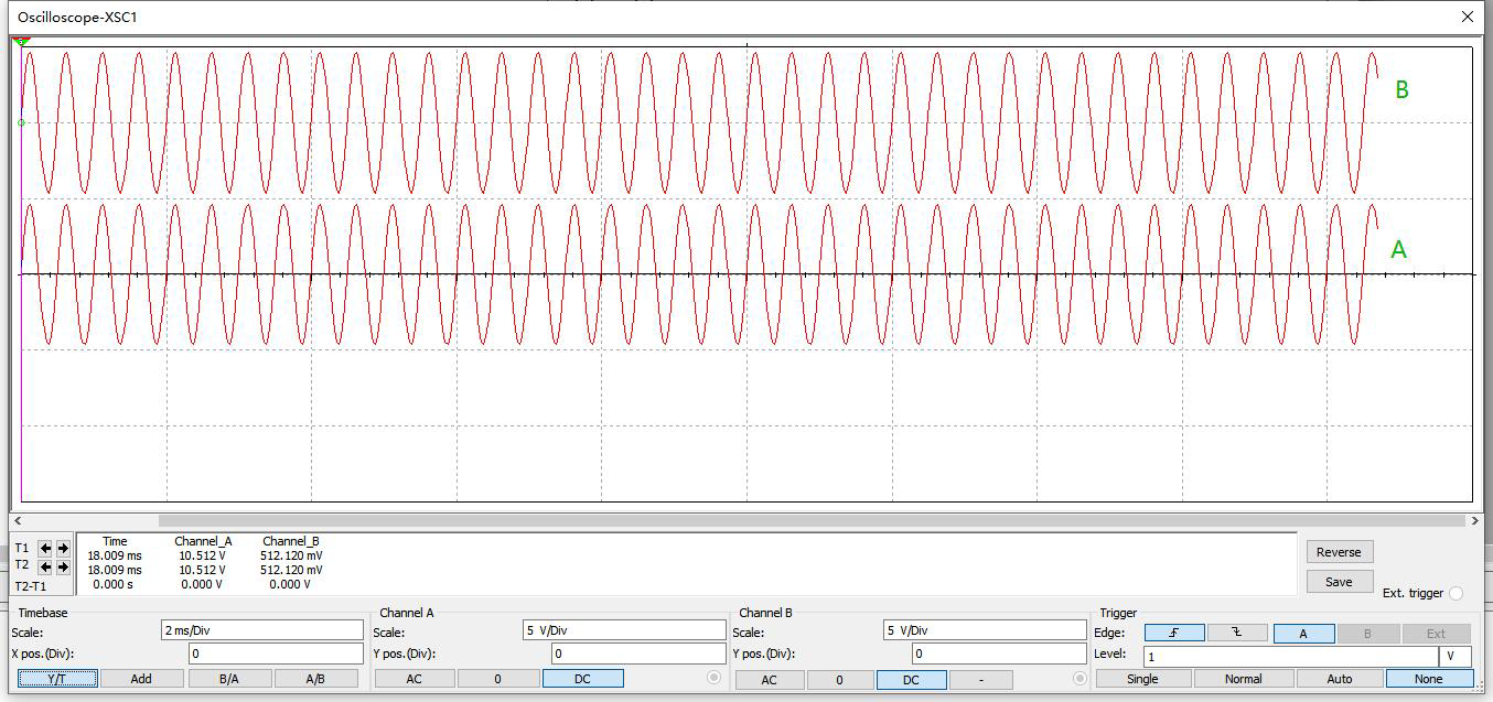
The simulation waveform is shown below:
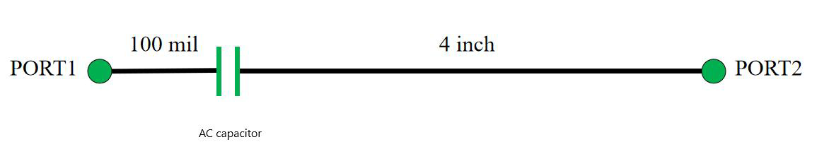
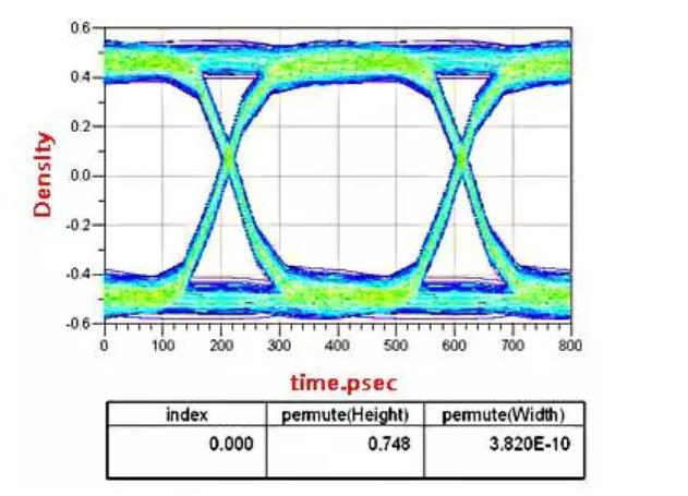
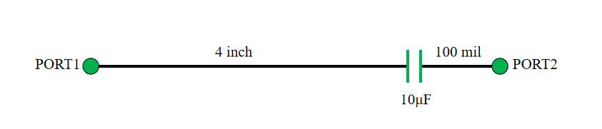
Below, we will analyze the placement position and capacitance size of AC capacitors. Location of 2 AC capacitors The following diagram shows an AC capacitor coupling circuit of a capacitor. Today, we will analyze the position of the AC capacitor based on this circuit:
In the design of circuit circuits, this capacitor can be equivalent to an ideal capacitor, and PORT1 and PORT2 can be considered as open circuits. In high-speed circuits, this capacitor cannot be equivalent to an ideal capacitor, and the frequency of the signal is 2.5G. 2.1 AC coupling capacitor placed at the sending end
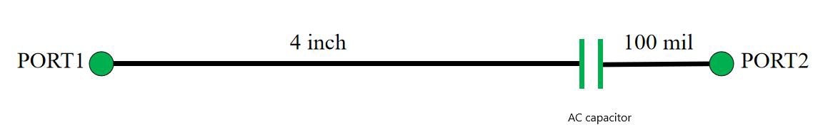
Place the AC capacitor at the sending end (PORT1), as shown in the specific circuit diagram:
The test eye diagram is as follows:
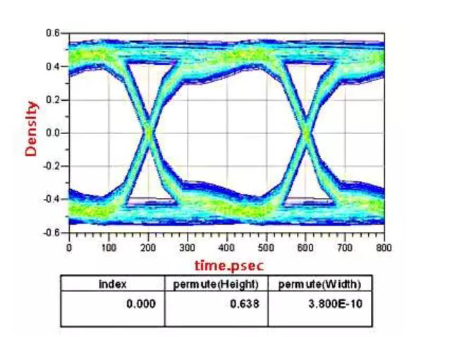
2.2 AC coupling capacitor placed at the receiving end
Place the AC capacitor at the sending end (PORT2), as shown in the specific circuit diagram:
The test eye diagram is as follows:
2.3 Result analysis
When the AC coupling capacitor is placed at the receiving end (PORT2), its performance is much better than that placed at the transmitting end (PORT1).
Analysis: The impedance of non ideal capacitors is discontinuous, and the energy reflected by the signal after channel attenuation will be less than the energy directly reflected. Therefore, the vast majority of serial links require this AC coupling capacitor to be placed at the receiving end. But there are also exceptions. The author has encountered this issue before when making board to board connections. Upon checking the PCIE specification, it was found that if two boards are usually placed on the sending end, another function of the AC coupling capacitor - overvoltage protection is also utilized. For example, SATA is usually required to be placed close to the connector.
Capacity value of 3 AC capacitors
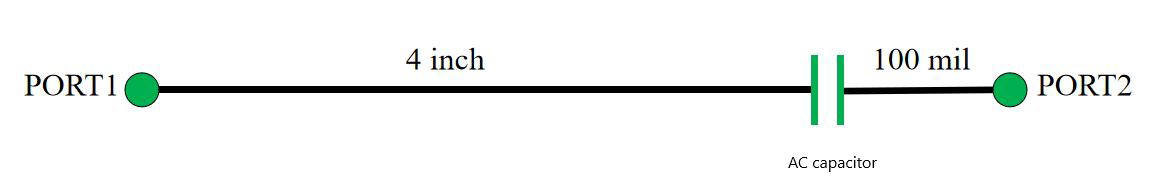
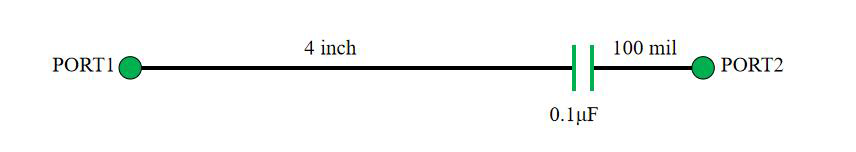
The signal link can be equivalent to a fixed resistor R, where the capacitance of the AC coupling capacitor affects the time constant τ, The larger the RC, the greater the DC component and the lower the DC voltage drop. Below we will analyze the capacitance value of AC capacitors: 3.1 0.1 μ F AC capacitor AC coupling capacitor adopts 0.1 μ F. The packaging is 0402, and the capacitor is located at the receiving end. The circuit is shown in the following figure:
The eye diagram for the test is as follows:

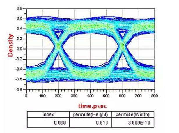
3.2 10 μ F AC capacitor
AC coupling capacitor adopts 10 μ F. The packaging is 0402, and the capacitor is located at the receiving end. The circuit is shown in the following figure:
The eye diagram for the test is as follows:
3.3 Result analysis
It can be seen that increasing the coupling capacitance leads to a decrease in eye height. Analysis: It is "high-speed" that causes the capacitance to become unsatisfactory. Inductive inductance will generate series resonance. The larger the capacitance value, the lower the resonance frequency. AC coupling capacitance is inductive at low frequencies, so the high-frequency component attenuation increases, the eye height decreases, the rising edge slows down, and the corresponding JITTER also increases. It is usually recommended that the AC coupling capacitance be between 0.01uf and 0.2uf, and 0.1uf is more common in projects. It is recommended to use the packaging of 0402.
Summary of 4 AC capacitors
Firstly, some protocols or manuals will provide design requirements, and we will place them according to the design guidelines.
(Analysis: Generally speaking, the position and capacitance size of the AC coupling capacitor are provided by the signal protocol or chip supplier. For different signals and chips, their position and capacitance size are different. For example, PCIE signals require the AC coupling capacitor to be close to the transmitting end of the channel, SATA signals require the AC coupling capacitor to be close to the connector, and for 10GBASE-KR signals, the AC coupling capacitor is required to be close to the receiving end of the signal channel. Secondly, if it is from IC to IC, please place it close to the receiving end.
Analysis 1: The capacitor is considered as an impedance discontinuity point (so it is required to match the transmission line as much as possible). If it is placed close to the receiving end and has the same reflection coefficient, the signal will undergo channel attenuation before being reflected, which will result in less energy than the initial reflection.). So most serial links require the receiver to play;
Analysis 2: During the signal transmission process, some DC components may also interfere with each other, leading to reception issues and proximity to the receiving end.
Analysis 3: After AD simulation, it was also found that the eye image quality effect is better when placed on the receiving end Thirdly, if it is an IC to connector, please place it close to the connector.
(Analysis: We know that AC coupling capacitors have another function, which is to provide protection against overvoltage and overcurrent. Therefore, in the case of connectors, this function happens to be played. Therefore, more requirements are to place them close to the connectors.) During the transmission of SATA signals, there will be attenuation, and the longer the transmission distance, the more severe the attenuation. Therefore, a carrier wave (i.e. DC component) will be given to it, and after entering the IC or SATA device, the DC component will be filtered out using a series capacitor method. This will have better signal quality, which is the effect of direct current isolation.
categories
recent posts


scan to wechat:everexceed