Power factor (hereinafter referred to as PF) is an important input parameter of all AC power equipment. When the input impedance characteristic of AC electrical equipment is resistive, capacitive or inductive, we call it linear load. The input power factor of this type of linear load is defined as the total change of the phase difference between the current and voltage at the input end, i.e. pf = COSO. The power factor generated by the phase difference between the current and voltage is called phase shifted power factor PF.
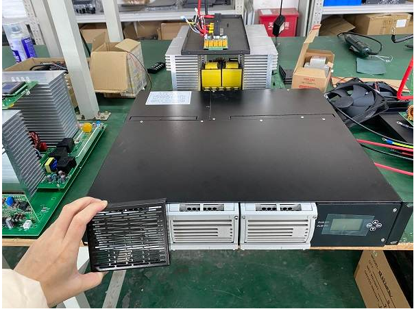
Power factor compensation of high frequency switching rectifier
When the AC power supply supplies power to the linear load, how much active power the linear load can get is only related to the input phase shift power factor PF. This phase shift power factor is easy to compensate. Generally, the mutual compensation of inductance and capacitance can improve the input phase shift rate factor of AC power equipment.
The input reactance characteristic of high frequency switching rectifier used in modern communication power supply is nonlinear. Its principle circuit diagram. The rectified DC pulsating voltage charges the filter capacitor. Every time it is charged to half a pulsating period, the voltage at both ends of the capacitor C is charged to the peak value V of the pulsating voltage. Then, the rectifier diode D. or D is turned off, and the capacitor C discharges to the load resistor R. when the voltage at both ends of the capacitor C drops to the extension rectifier transistor D. or D.
When conducting, the AC power supply momentarily charges the capacitor C. Since the charging time is very short, about 2-4ms, the current waveform is a very narrow current peak. According to Fourier analysis, this peak current waveform is composed of 50Hz fundamental wave current and multiple harmonic current, and the frequency of each harmonic current is an integral multiple of the fundamental wave frequency.
Since the voltage waveform is a sine wave without harmonic components, only the product of the effective value of the fundamental current and the effective value of the sinusoidal voltage is the active power consumed by the load resistor R. Therefore, the harmonic current cannot generate active power. The harmonic current only exchanges reactive power between the power supply and the input terminal of the AC electric equipment. Although the harmonic current does not work on the load R, it occupies a part of the input current, that is, it increases the input apparent power.
In this nonlinear rectified load, the amount of active power obtained on the load r only depends on the distortion power factor pfxx, and the distortion power factor is defined as.
PF ★ = i n = (2k-1), k = 1,2,3,4... (3-11) where 1 is the fundamental wave current of distortion current wave; Ia,Is,•…,I。, It is the 3rd, 5th and Nth harmonic current of distortion wave current. There is no even harmonic in the distortion current.
It can be seen from equation (3-11) that when the harmonic current of more than 3 times (including 3 times) in the input current is zero, the distortion power factor has the maximum value, i.e. pf * a = 1. At this time, the input apparent power is all converted into the active power of the load resistor R. Total input power factor PF of electric equipment. The relationship with phase shift power factor PFM and distortion power factor pf * is:
PFa=PFXPF (3-12)
The phase difference between the distorted current waveform and the sine wave voltage waveform is very small. According to the test results, PF * g = 0.98 ~ 0.99. According to equation (3-12), the total input power factor PF of the high-frequency switching rectifier can be seen. Which mainly depends on the distortion power factor PF.
The power factor PFS of single-phase input high-frequency switching rectifier without power factor compensation can generally reach about 0.7, and the power factor PFA of three-phase input can generally reach 0.8 ~ 0.85. Due to the low input distortion power factor, the power grid must provide a large harmonic current to meet the requirements of the apparent input power of the electrical equipment. In order to measure the relative content of harmonic current, the relative content of total harmonic current, i.e. THDi (total harmonic distortion, I represents current harmonic), is introduced during harmonic current analysis.
The above is the power factor compensation of the high-frequency switching rectifier, and all the contents that the distortion power factor has the maximum value.
If you have any requirements or any kind of query regarding the rectifier solutions for your applications, feel free to communicate with our dedicated team at any time at marketing@everexceed.com.
tags :
categories
recent posts


scan to wechat:everexceed