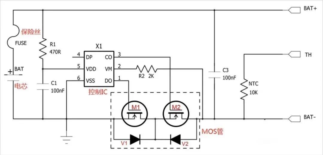
In the above figure, the control IC controls the MOS switch to turn on and off the circuit to protect the circuit, and FUSE realizes secondary protection on this basis; TH is temperature detection, and the inside is a 10K NTC; NTC mainly realizes temperature detection; TVS Mainly to suppress the surge.
(1) Primary protection circuit
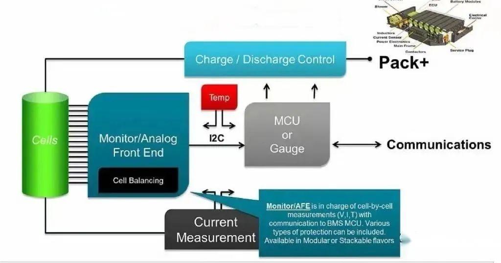
Control IC The control IC in the figure above is responsible for monitoring the battery voltage and loop current, and controlling the switches of two MOSs. The control IC can be divided into AFE and MCU: AFE (Active Front End, analog front-end chip) is the sampling chip of the battery, which is mainly used to collect the voltage and current of the battery cell. MCU ((Microcontroller Unit, microcontroller chip) mainly calculates and controls the information collected by AFE.
The relationship between the two is shown in the figure:
1. AFE
AFE is generally a 6-pin chip, CO, DO, VDD, VSS, DP and VM, the introduction is as follows:
CO: charge output (charge control);
DO: discharge output (discharge control);
VDD: power supply voltage, also known as output voltage, is the place with the highest voltage;
VSS: reference voltage, which is the place with the lowest voltage;
VM: Monitor the voltage value across the MOS.
When BMS is normal, CO, DO, VDD are high level, VSS, VM are low level, when any parameter of VDD, VSS, VM changes, the level of CO or DO terminal will change.
2. MCU
MCU refers to a micro control unit, also known as a single-chip microcomputer, which has the advantages of high performance, low power consumption, programmable, and high flexibility. It is widely used in consumer electronics, automobiles, industry, communications, computing, home appliances, medical equipment and other fields. In a BMS, the MCU acts as the brain, capturing all the data from the sensors through its peripherals and processing the data to make appropriate decisions based on the profile of the battery pack. The MCU chip processes the information collected by the AFE chip, and plays the role of calculation (such as SOC, SOP, etc.) and control (MOS off, on, etc.), so the battery management system has high requirements on the performance of the MCU chip. AFE and MCU realize the protection to the circuit by controlling MOS.
3.MOS
MOS is the abbreviation of Metal-Oxide-Semiconductor Field-Effect Transistor, referred to as field effect transistor, which acts as a switch in the circuit and controls the on and off of the charging circuit and the discharging circuit respectively. Its on-resistance is very small, so its on-resistance has little effect on the performance of the circuit. Under normal conditions, the consumption current of the protection circuit is μA level, usually less than 7μA.
4. Realization of BMS primary protection: linkage between control IC and MOS
If the lithium battery is overcharged, overdischarged or overcurrented, it will cause chemical side reactions inside the battery, which will seriously affect the performance and service life of the battery, and may generate a large amount of gas, which will rapidly increase the internal pressure of the battery and eventually lead to pressure release. The valve opens and the electrolyte is ejected to cause thermal runaway.
When the above situation occurs, the BMS will activate the protection mechanism and execute as follows:
(1) Normal state
In normal state, both "CO" and "DO" pins in the circuit output high level, both MOSs are in conduction state, and the battery can be charged and discharged freely.
(2) Overcharge protection
When charging, AFE will always monitor the voltage between pin 5 VDD and pin 6 VSS. When this voltage is greater than the overcharge cut-off voltage, MCU will control pin 3 CO (CO pin changes from high level to low level) Ping) to close the MOS tube M2, at this time the charging circuit is cut off, and the battery can only be discharged. At this time, due to the existence of the body diode V2 of the M2 tube, the battery can discharge the external load through this diode.
(3) Over-discharge protection
When discharging, AFE always monitors the voltage between pin 5 VDD and pin 6 VSS. When this voltage is lower than the over-discharge cut-off voltage, MCU will pass pin 1 DO (DO pin changes from high level to low level) Turn off the MOS tube M1, then the discharge circuit is cut off, and the battery can only be charged. At this time, due to the existence of the body diode V1 of the MOS transistor M1, the charger can charge the battery through the diode.
(4) Overcurrent protection
During the normal discharge process of the battery, when the discharge current passes through two MOSs in series, a voltage will be generated at both ends due to the on-resistance of the MOS. The voltage value U=2IR, and R is the on-resistance of a single MOS. AFE pin 2 VM will monitor the voltage value all the time. When the loop current is so large that the voltage U is greater than the overcurrent threshold, the MCU will turn off the MOS transistor M1 through the first pin DO (DO pin changes from high level to low level), and the discharge loop is cut off, so that the current in the loop is zero. , to play the role of overcurrent protection.
(5) Short circuit protection
Similar to the working principle of overcurrent protection, when the loop current is so large that the voltage U instantly reaches the short-circuit threshold, the MCU will turn off the MOS tube M1 through the first pin DO (DO pin changes from high level to low level), and cut off The discharge circuit acts as short circuit protection. The delay time of short-circuit protection is very short, usually less than 7 microseconds.
The above can be briefly described as:
|
Circuit status |
MOS1 |
MOS2 |
Charge and discharge status |
|
Normal status |
ON |
ON |
Rechargeable and dischargeable |
|
Over charge protection |
ON |
OFF |
Dischargeable and non-rechargeable |
|
Over discharge protection |
OFF |
ON |
rechargeable non-dischargeable |
|
Over current protection |
OFF |
ON |
When the overcurrent is released, it can be charged and discharged |
|
Short circuit protection |
OFF |
ON |
When the short circuit is released, it can be charged and discharged |
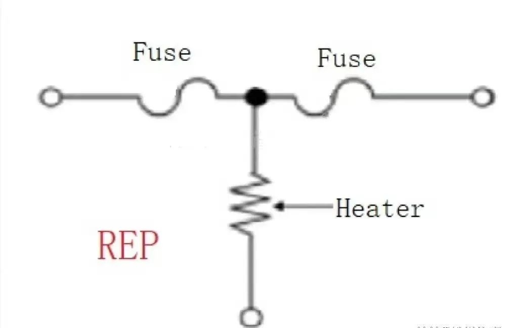
(2) Secondary protection circuit: three-terminal fuse Fuse
For security reasons, a secondary protection mechanism still needs to be added. At the current stage, REP (Resistor Embedded Protector, built-in resistance protector) is highly applied, while the three-terminal fuse Fuse is more cost-effective in comparison.
When the current is too large, the Fuse will be blown in the same principle as the ordinary fuse; and when the MOS is in an abnormal operating state, the main control will automatically blow the three-terminal fuse. The main advantages of this security protection mechanism are low power consumption, fast response speed, and good protection effect. At this stage, it has high applicability and has been widely used in electric vehicles, mobile phones and other equipment.
 |
|
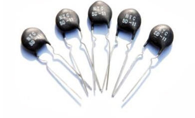
Three-level protection circuit: NTC and TVS1.NTC thermistor Thermistor, which is extremely sensitive to heat, is a kind of variable resistor, mainly divided into PTC and NTC. PTC (Positive Temperature Coefficient, positive temperature coefficient thermistor), the higher the temperature, the greater the resistance, mainly used in mosquito killers, heaters and other products. NTC (Negative Temperature Coefficient, Negative Temperature Coefficient Thermistor) is the opposite of PTC. The higher the temperature, the lower the resistance. It is mainly used as a resistance temperature sensor and a current limiting device. |
(1) Temperature measurement
Using the characteristics of this resistor, the following three temperature categories can be measured: Cell temperature: Place the NTC thermistor between the cells to measure the cell temperature, and the number of cells covered by each NTC needs to be considered. Power temperature: Place the NTC thermistor between the MOS to measure the power temperature. It is necessary to ensure that the NTC is in close contact with the MOS device during installation. Ambient temperature: place the NTC thermistor on the BMS board to measure the ambient temperature, and the installation location is required to be far away from the power device.
(2) Temperature compensation
The resistance of most components will increase as the temperature rises. At this time, NTC needs to be used for compensation to offset the error caused by temperature.
(3) Suppress inrush current
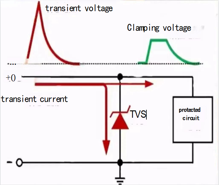
Surge (electrical surge), also known as surge, is the momentary peak value beyond the stable value, including surge voltage and surge current. When the electronic circuit is turned on, it will generate a large surge current, which is easy to cause damage to the components. Using NTC can prevent this from happening and ensure the normal operation of the circuit. For surge protection, TVS is needed.
2. TVS transient voltage suppressor
TVS (Transient Voltage Suppressors) are transient voltage suppressors, which respond quickly and are suitable for port protection. The specific implementation is as follows:
categories
recent posts


scan to wechat:everexceed